Mud Motors
Downhole Motors
Prime Horizontal’s Mud motor (or Drilling Motor) is a Progressive Cavity Positive Displacement Pump (PCPD) placed in the Drill string to provide power to the bit while drilling by using the drilling mud to create eccentric motion in the power section of the motor. The Mud Motor uses different rotor and stator configurations to provide greater horsepower for the desired drilling operation, as the eccentric motion in the power section is transferred as concentric power to the drill bit. The rotation rate of the bit is proportional to the volumetric flow rate of drilling mud through the motor and normal rotation rates are from 60 rpm, to over 150 rpm.

Figure 1: Schematic diagram of Mud Motor
Six different drilling motors can be provided for bit sizes ranging from 4 ¾ in. to 12 ¼ in. as shown in Table 1:
Table 1: Prime Horizontal Mud Motor Specifications
| Table 1: prime horizontal mud motor specifications | |||||
|
Motor |
Min Bit size (in.) |
Max Bit Size (in.) |
Tool OD (in.) |
Stages |
See following PDF file for Detailed Specifications |
| PH-312-560-30 |
3 7/8 |
4 1/2 |
3 1/8 |
3.0 |
PH-312-560-30.pdf |
| PH-375-560-30 |
4 3/4 |
5 7/8 |
3 3/4 |
3.0 |
PH-375-560-30.pdf |
| PH-375-910-40 |
4 3/4 |
5 7/8 |
3 3/4 |
4.0 |
PH-375-910-40.pdf |
| PH-475-780-50 | 6 | 7 7/8 | 4 3/4 |
5.0 |
PH-475-780-50.pdf |
| PH-475-910-40 |
6 |
7 7/8 |
4 3/4 |
4.0 |
PH-475-910-40.pdf |
| PH-675-910-40 |
7 7/8 |
9 7/8 |
6 3/4 |
4.0 |
PH-675-910-40.pdf |
| PH-800-670-40 |
9 7/8 |
12 1/4 |
8 |
4.0 |
PH-800-670-40.pdf |
| PH-800-910-40 |
9 7/8 |
12 1/4 |
8 |
4.0 |
PH-800-910-40.pdf |
Detailed specifications are provided in the above listed PDF files:
The bend angle of the mud motor, called the angle of inclination, is set on the tool by following the instructions below.
1. Adjust the angle of inclination
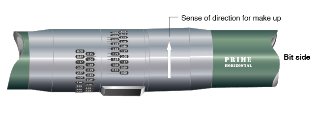
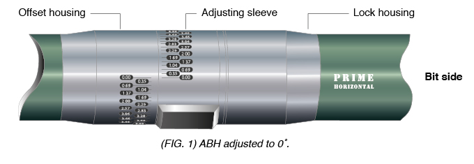
For adjusting the angle of inclination please perform the following 5 steps. (Fig. 1)
In this example the angle of inclination will be adjusted from 0˚ to 1,37˚.
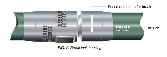
Step 1: Break lock housing
- Break the lock housing and unscrew the thread until the gap between the shoulders of the lock housing and the adjusting sleeves amounts approx. 15mm. (Fig. 2)
ADVICE
While breaking the lock housing it could happen that the gear tooth system between offset housing and adjusting sleeve gets out of engage. This has to be prohibited to avoid the break of the thread connection between offset housing and double pin.
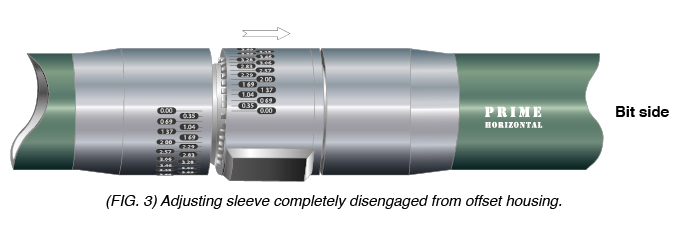
Step 2: Loosening the gear tooth system out of engagement
- Move the adjusting sleeve in direction to the lock housing, until the gear teeth of the adjusting sleeve is completely out of engagement with the gear teeth of the offset housing
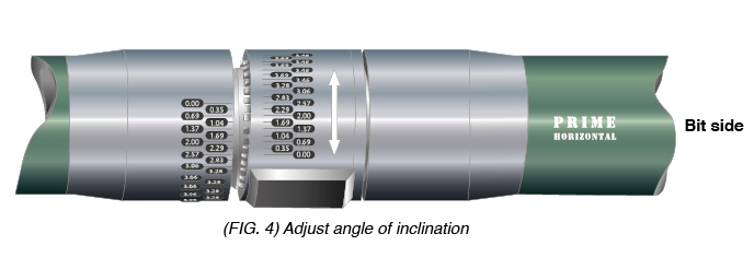
Step 3: Adjust the angle of inclination
!!ATTENTION!!
The adjusting sleeve must not be turned more than 180˚.
- Always turn the adjusting sleeve in that direction which leads tot he shortest way, until the designated angle numbers of the adjusting sleeve and the offset housing are matching. (Fig. 4)
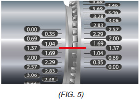
- The designated angle of inclination is set as far as the same degree numbers of the adjusted sleeve and the offset housing are (Fig. 5)
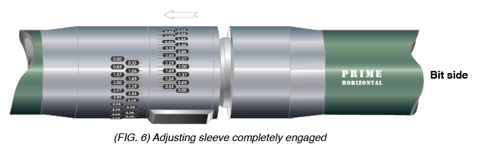
Step 4: Engage back gear teeth of adjusted sleeve
- Move the adjusting sleeves in direction to the offset housing, until the gear teeth of the adjusting sleeve are completely engaged to the gear teeth of the offset housing.
ADVICE
Ensure that the designated angle of inclination is still adjusted.
Step 5: Make up lock housing
- Move up the lock housing according to the make up torque.
ADVICE
Ensure that the gear tooth system does not slip out of engagement while torquing up adjusting sleeve and offset housing.
