HDD Magnetic Sources
ParaTrack-2 uses selectable magnetic sources to fit the requirements of the most exacting HDD or CBM project, and it is the only HDD steering system on the market designed for guidance with AC electromagnetic field sources. The signal to electromagnetic noise ratio is much better for AC magnetic fields than for DC magnetic fields which allows better tracking accuracy at deeper depths and in noisier magnetic environments. The use of AC fields has also spurred the development of an entire suite of different magnetic sources by Prime Horizontal and Vector Magnetics which are used for different HDD applications, each source having different specifications of accuracy and precision. It is not uncommon for the same HDD project to use several different magnetic sources with the ParaTrack 2 system, depending on the geometry and precision requirements of the project. Ask for our case history on the Le Havre Project to note the use of four different magnetic sources with ParaTrack 2.
 Guidewire Magnetic Source
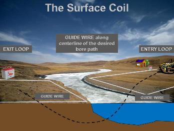
For many crossing projects, a guidewire is deployed all the way from entry to exit, either on the surface or on the sea bottom, through which is passed a DC electromagnetic field (ParaTrack-1) or an AC electromagnetic field (ParaTrack-2) to enable pilot hole tracking accurately along its length. The guidewire may be deployed as a single wire or as a closed loop. The continuous tracking reduces the probability of pull-backs, sidetracks and corrections.
AC Beacon
The AC Beacon is used primarily for shore approaches and long crossings. The AC beacon provides accurate positioning up to 100 meters so installing a beacon with ParaTrack 2 periodically along a long crossing allows the use of shorter guidewires. For more details, have a look at our brochure, AC Beacon.
RM and AM Magnetic Sources
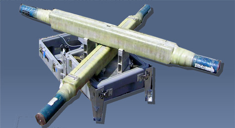
The Rotating Magnet is routinely run as a bit sub located just behind the drill bit. It is The Rotating Magnet is routinely run as a bit sub located just behind the drill bit. It is used as a target (1) for HDD Intersect Operations; (2) for Coal Bed Methane (CBM) production wells; (3) for guiding parallel freeze holes inside rail tunnels & auto tunnels; (4) for placement inside the RM benchmark for very long HDD Crossings; and (5) for tracking parallel bore holes in vertical and horizontal holes.
When configured with bar magnets oriented parallel to one another, all perpendicular to the long axis of the sub, the tool is named the RM Sub. When configured with rare earth magnets instead of bar magnets, the bit sub is referred to as the AM Sub.
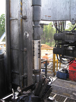 Figure RM1. The RM sub set up for a vertical well CBM project. Nine locations of bar magnets are visible from this view, although 15 bar magnets were used. The others can be seen after the sub is slightly rotated.
When the drill bit spins, the rotation of the RM sub (or AM sub) generates an AC electromagnetic field which is detected at the steering tool for all applications. Quite simple and foolproof in concept, the rotation rate of the RM source is the same as the rotation rate of the spinning bit.
The magnetic field strength of the RM sub may be changed by the operator and optimized for use on each job, based on that job’s unique characteristics. Used on an approach to the intersection point in an intersect project, the EM field of the Rotating Magnet can be detected up to 70 meters in front of the bit. Used for the final approach to that intersection point, the RM sub gives centimeter accuracy of its relative position to the target bore. Since the EM field strength drops with distance from the magnets according to the inverse square law, an optimum number of magnets is normally chosen for Initial Approach operations in an intersect project while a small number of magnets is chosen for Final Approaches. Final approach precision is improved if the axial magnets are used rather than the bar magnets, but in this case, the total distance from magnets to steering tool is smaller since the axial magnets are more range limited than the bar magnets.
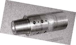 Figure RM2. The Axial Magnet, shown here, is made for low EM field strength operations where close tolerance is required. These applications include final approaches for HDD intersects and closely spaced boreholes in tunnels. Vertical operations are possible where the AM Sub is raised and lowered on a wire line. Centimeter measurement accuracy is obtained when operated within specifications.
MicroCoil Source
When tunneling in very soft formations allowing tunnel collapse or in severely fractured formations allowing drilling fluids to communicate with the surface, extreme care must be taken with the tunneling method. Freeze drilling has been the solution to date and this solution works, especially when used with Prime’s MicroCoil source designed especially for such an application.
It is commonly understood that passing an electric current through a coil of wire will generate a uniform magnetic field especially within the area enclosed by the coil. It has also been commonly understood that as the radius of the coil approaches zero, the net magnetic flux approaches zero since the flux from one side of the coil cancels out the flux from the other side. While this is, in principle true, what was not realized is that for small but still reasonable radii of the coil, there is still sufficient signal strength to use the coils as a magnetic source for the accurate placement of pilot holes which are filled with the freezing brine in a freeze drilling operation. Prime Horizontal has used this method successfully in the construction of a new metro station in Naples, and more recently in the Hallandsas Rail Tunnel still underway.
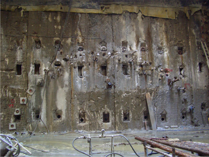 Figure Microcoil1. One of the Metro channels being configured for drilling of the pilot holes to carry freezing brine so the Metro tubes could be bored. About half of the pilot holes have been drilled.
 Figure Microcoil2. CAD drawing of one of the Metro channels.
The holes are on 0.5 meter centers and they are each about 50 meters in length. When they are finished, freezing commences. An annulus of About 1 m – 1.5 meter is totally frozen at which point a TBM is used to excavate the 50 meters. When the 50 meters is excavated, the next set of pilot holes is drilled. This process continues until the entire Metro bore is finished. Tolerances are extremely critical since if two adjacent pilot holes were to intersect, the freezing process would be stopped due to lost circulation. The MicroCoil source kept the pilot hole drilling on track.
RM Benchmark Source
Using a Rotating Magnet (RM) source deployed in a known position on the sea bed or river bottom will generate an AC magnetic field observable by the ParaTrack sensors in the steering tool to a distance in excess of 70 meters below the location of the RM Benchmark. Elevation and more importantly, the left/ right position of the bore can then be measured at deployed points along the axis of the bore path thus guaranteeing positional accuracy when reaching areas of more conventional methods of determining positions.
The RM Benchmark System was developed to provide navigation beacons at known
Locations underwater along the center line of the bore path. These positions are then used to fine tune or calibrate the base line azimuth which can suffer magnetic interference from the motor, drill pipe or various local magnetic anomalies in the area.
The RM Benchmark allows navigation corrections at positions where conventional surface guidewires are impossible or impractical to install. For long crossings, it is not uncommon for several benchmarks to be used spread out like a string of pearls along the water bottom until a conventional surface guidewire can be used once more.
Intersect Drilling Projects, Shore Approaches and Long Distance water crossings all have benefited from use of the RM Benchmarks.
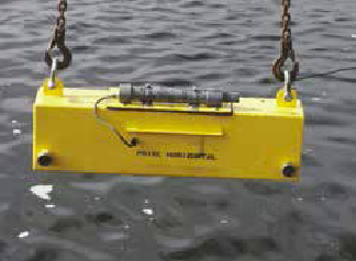 Figure Benchmark1. The RM Benchmark being deployed. Its weight in air is 125 kg. The box is approximately 1 m x 0.2 m x 0.28 m.
For more details, download the RM Benchmark Brochure.

